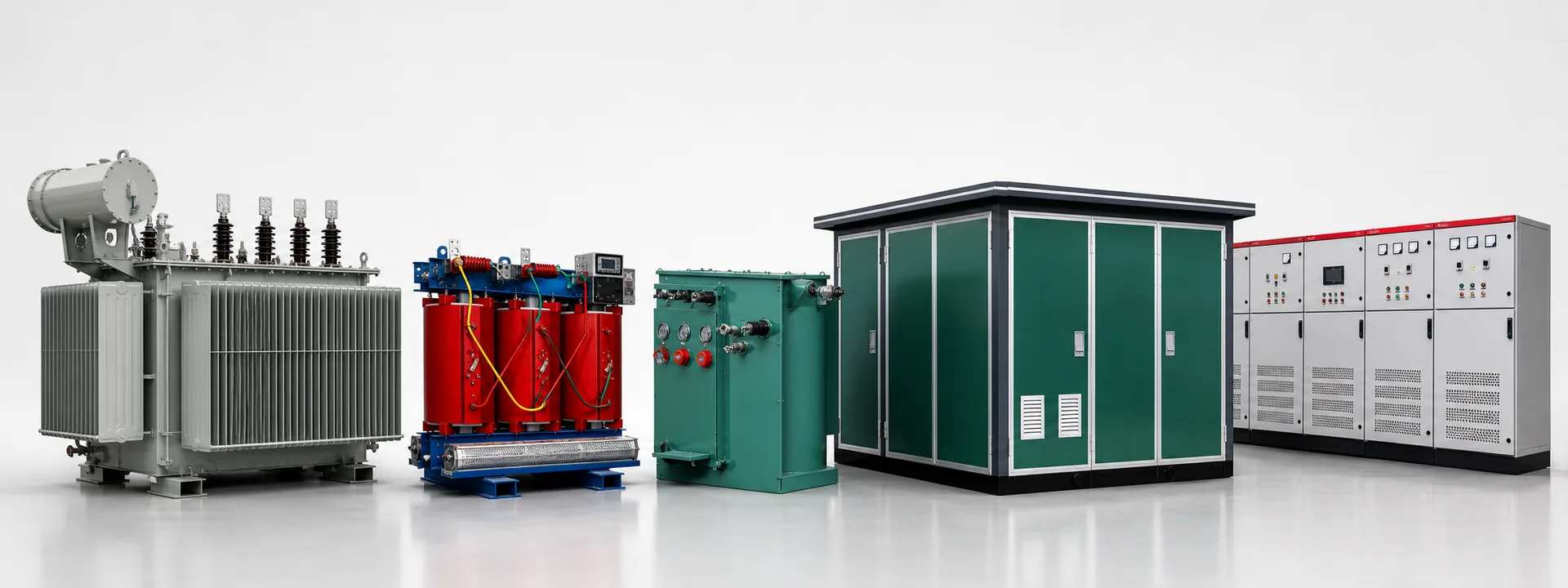
IEC 60076-1 & IEEE C57.12 PHASE DISPLACEMENT
Transformer Vector Groups Explained: Dyn11, YNd11 & Yyn0
Selecting the wrong vector group can cause severe third-harmonic voltage distortion, unbalanced neutral shift, or catastrophic circulating currents when paralleling units. Master clock-hour notation and utility selection rules.
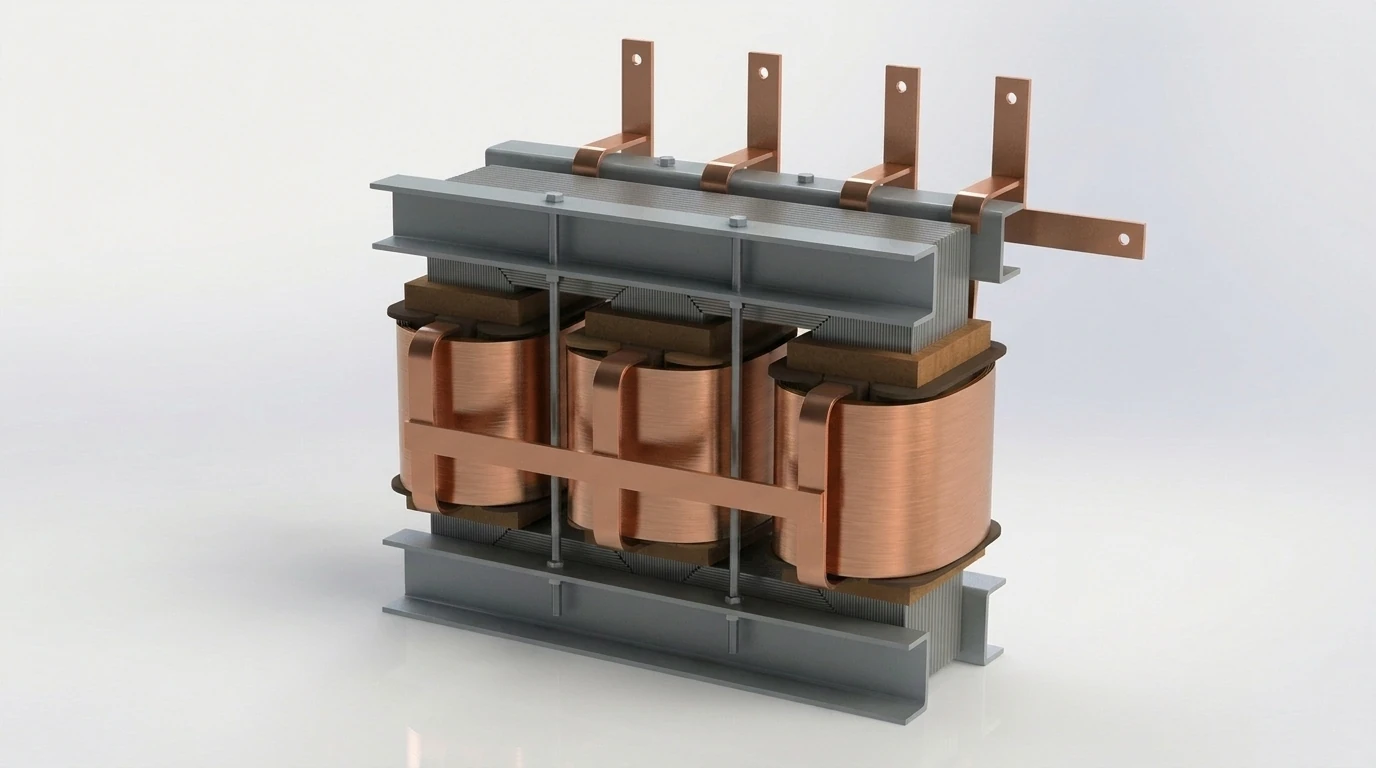
IEC 60076-1 NOTATION
How to Decode Any Vector Group Symbol
Every IEC vector group code follows a strict order: [HV Winding][LV Winding][Clock Number]. Uppercase letters (D, Y, Z) always denote the high-voltage side; lowercase letters (d, y, z) denote the low-voltage side. The letter N or n indicates an externally accessible neutral terminal.
The clock number represents the phase angle lag of the LV line-to-neutral phasor relative to the HV phasor in multiples of 30° (e.g., 11 = 11 × 30° = 330° lag, which equals +30° lead; 1 = 30° lag; 0 = 0° in-phase).
SELECTION MATRIX
Most Common Industrial & Utility Vector Groups
| Vector Group | Phase Shift | Primary Benefit | Typical Application |
|---|---|---|---|
| Dyn11 | +30° (LV leads HV) | Traps 3rd harmonics; handles 100% single-phase unbalance | IEC 11 kV / 33 kV to 400V/230V distribution & data centers |
| Dyn1 | -30° (LV lags HV) | ANSI standard angular displacement | North America / 60 Hz pad-mounted & utility networks |
| YNd11 | +30° (LV leads HV) | Grounded HV star neutral + delta LV harmonic trap | 110 kV / 33 kV grid substations & power plants |
| Yyn0 | 0° (In-phase) | Lower HV insulation cost; no phase shift | Balanced 3-phase motor loads (≤25% neutral unbalance) |
| Dd0 / Yy0 | 0° (In-phase) | Paired with Dy11 for 12-pulse phase shifting | Solar PV / VFD rectifier converter systems |
SUBSTATION PARALLELING
4 Mandatory Conditions for Parallel Operation
- 1. Identical Vector Group (Mandatory): Both transformers must have the exact same clock number (e.g., Dyn11 with Dyn11) and phase sequence.
- 2. Equal Voltage Ratio (≤0.5% tolerance): Open-circuit secondary voltage difference must stay within 0.5% across active tap settings to avoid circulating current.
- 3. Matching Impedance Voltage (%Uk within ±10%): Transformers share load inversely proportional to their percent impedance; mismatched %Uk causes one unit to overload prematurely.
- 4. kVA Capacity Ratio ≤ 3:1: Avoid paralleling units differing by more than 3× in rated kVA capacity.
CUSTOM WINDING ENGINEERING
Need a Specific Vector Group?
XinHuan winds custom Dyn11, Dyn1, YNd11, Yyn0, Dd0, and multi-winding phase-shifting units tested to IEC 60076-1 polarity & phase displacement verification.