What is YRM6-12 / YRM6-24 Gas-Insulated Switchgear?
YRM6-12/24 is a fully insulated, fully enclosed SF6 gas-insulated compact switchgear and Ring Main Unit (RMU). It integrates primary medium-voltage components (load break switches, vacuum circuit breakers, disconnectors, and earthing switches) inside a 3.0mm thick, laser-welded 304 stainless steel gas chamber filled with SF6 gas at 1.4 bar absolute working pressure.
Because all high-voltage live parts are completely isolated from external ambient atmosphere, the YRM6 unit offers IP67 hermetic protection. It is completely immune to moisture, airborne dust, heavy salt spray, chemical corrosion, flood submersion, and extreme ambient temperatures (-40°C to +40°C).
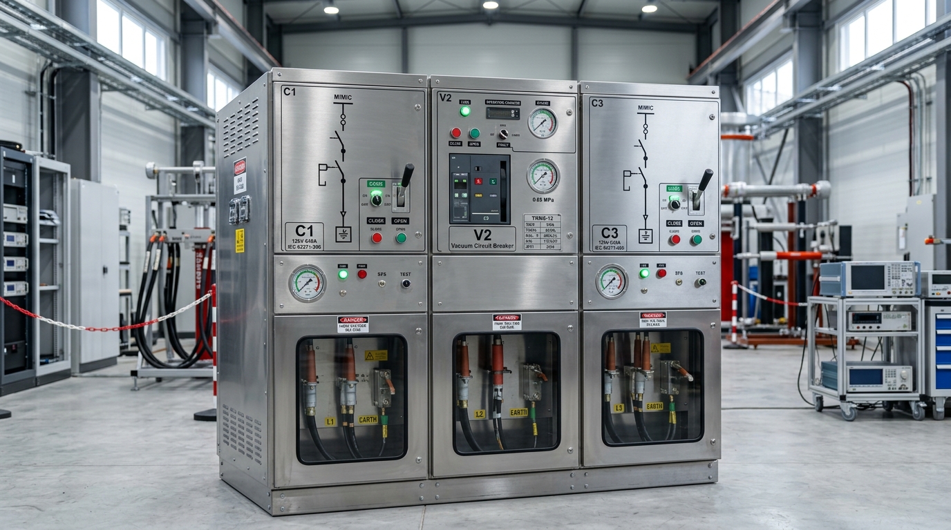
Standard module panel width is only 325mm (12kV) or 375mm (24kV), saving up to 60% floor space compared to air-insulated switchgear (AIS).
Hermetically sealed SF6 gas room with an annual gas leakage rate below 0.25%/year. Operates 30+ years without internal switch servicing.
Features 3-position load/earth switches with reliable mechanical interlocking between cable room doors and load switches, plus arc pressure relief channels.
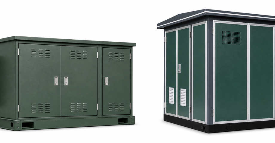
Ideal for underground vaults, coastal marine platforms, high-altitude mines (up to 1500m+ derated), and outdoor compact package substations.
Decoding YRM6 Modular Configuration Codes (C, V, F, CVC, CCV)
YRM6 switchgear utilizes a standardized single-letter module coding system. Individual functional modules can be combined inside a single common SF6 gas chamber (up to 6 modules per tank) or expanded infinitely via top/side plug-in shielded extension busbars.
1. Standard Single Functional Module Types
| Code | Module Name | Function & Components | 12kV Width | 24kV Width |
|---|---|---|---|---|
| C | Load Break Switch Module | 630A 3-position load/earth switch. For incoming and outgoing network loop control. Includes cable bushings and earth switch interlock. | 325 mm | 375 mm |
| V | Vacuum Circuit Breaker Module | 630A / 1250A VCB with spring mechanism and protection relay. Used for transformer protection or heavy feeder circuit breaking (20kA / 25kA). | 325 mm | 375 mm |
| F | Load Switch & Fuse Combination | 630A load switch combined with HV current-limiting fuses. Economical short-circuit protection for transformers up to 1250kVA / 2500kVA. | 325 mm | 375 mm |
| D | Direct Cable Connection / Riser | Direct cable connection module without grounding switch. Used for busbar riser or incoming cable connection. | 325 mm | 375 mm |
| SL | Busbar Section Switch (LBS) | Busbar segmentation module using a 630A load break switch for bus section isolation. | 325 mm | 375 mm |
| SVBR | Busbar Section Switch (VCB) | Busbar segmentation module using a vacuum circuit breaker combined with bus riser. | 650 mm | 650 mm |
| M | Metering Module (12kV/24kV) | Air-insulated or gas-insulated metering panel equipped with current transformers (CT) and potential transformers (PT) for revenue billing. | 695 mm | 695 mm |
2. Popular Multi-Circuit Combination Units
In practice, switchgear units are specified by combining module letters. Here are the most widely specified standard factory configurations:
YRM6-12-CVC
3 Circuits (approx 310kg)Configuration: C (Incoming LBS) + V (Transformer Protection VCB) + C (Outgoing LBS).
Primary Application: The standard 3-way Ring Main Unit for distribution substations where a vacuum circuit breaker protects the main power transformer while dual load switches maintain loop line connection.
YRM6-12-CCV
3 Circuits (approx 310kg)Configuration: C (Incomer 1 LBS) + C (Incomer 2 LBS) + V (Vacuum Circuit Breaker Feeder).
Primary Application: Dual-incomer loop switching with 1 VCB feeder for industrial factory intake rooms.
YRM6-12-CCF
3 Circuits (approx 320kg)Configuration: C (LBS) + C (LBS) + F (Load Switch + Fuse Combo).
Primary Application: Compact package substations and kiosk units where fuse protection is preferred for transformers up to 1000kVA.
YRM6-12-CCFF / CCVV
4 Circuits (approx 410kg–430kg)Configuration: 2 Loop Incomers + 2 Fuse-protected or VCB Feeders.
Primary Application: Commercial shopping complexes, dual-transformer substation vaults, and industrial park branch nodes.
Comprehensive Electrical Technical Parameters
All YRM6 switchgear units are manufactured and tested in strict accordance with IEC 62271-200, IEC 62271-100, IEC 62271-102, and GB/T standards.
| No. | Technical Parameter | Unit | Load Break Switch (C) | Fuse Combination (F) | Vacuum Breaker (V) |
|---|---|---|---|---|---|
| 1 | Rated Voltage | kV | 12 / 24 | ||
| 2 | Rated Frequency | Hz | 50 / 60 | ||
| 3 | Power Frequency Withstand (1 min) — Phase to Phase / Earth | kV | 42 / 65 | 42 / 65 | 42 / 65 |
| 4 | Power Frequency Withstand — Across Open Contacts | kV | 48 / 75 | 48 / 75 | 48 / 75 |
| 5 | Lightning Impulse Withstand (1.2/50μs) — Phase to Phase / Earth | kV | 75 / 125 | 75 / 125 | 75 / 125 |
| 6 | Lightning Impulse Withstand — Across Open Contacts | kV | 85 / 145 | 85 / 145 | 85 / 145 |
| 7 | Rated Busbar Current | A | 630 | 630 | 630 / 1250 |
| 8 | Rated Short-Time Withstand Current (4s) | kA | 20 / 25 | --- | 20 / 25 |
| 9 | Rated Peak Withstand Current | kA | 50 / 63 | --- | 50 / 63 |
| 10 | Rated Short-Circuit Making Current (Peak) | kA | 50 / 63 | 80 / 80 | 50 / 63 |
| 11 | Rated Short-Circuit Breaking Current | kA | --- | 31.5 / 31.5 | 20 / 25 |
| 12 | SF6 Gas Pressure @ 20°C (Absolute) | bar | 1.4 bar (0.04 MPa gauge pressure) | ||
| 13 | Annual SF6 Leakage Rate | %/yr | ≤ 0.25% / year | ||
| 14 | Enclosure Protection Rating | IP | SF6 Gas Room: IP67 | Fuse Canister: IP67 | Outer Enclosure: IP3X / IP54 | ||
| 15 | Mechanical Life | ops | 5,000 | 3,000 | 5,000 |
HV Current-Limiting Fuse Selection Table for Transformer Protection
When specifying YRM6-12/24 Module F (Load Break Switch + HV Fuse Combination), selecting the correct high-voltage current-limiting fuse rating (Amps) according to primary voltage (kV) and transformer capacity (kVA) is essential to ensure full-range overload and short-circuit protection.
| HV Voltage (kV) | Rated Transformer Capacity (kVA) | |||||||||||||||
|---|---|---|---|---|---|---|---|---|---|---|---|---|---|---|---|---|
| 25 | 50 | 75 | 100 | 125 | 160 | 200 | 250 | 315 | 400 | 500 | 630 | 800 | 1000 | 1250 | 1600 | |
| 3 kV | 16A | 25A | 25A | 40A | 40A | 50A | 50A | 80A | 100A | 125A | 160A | 160A | --- | --- | --- | --- |
| 3.3 kV | 16A | 25A | 25A | 40A | 40A | 50A | 50A | 63A | 80A | 100A | 125A | 160A | --- | --- | --- | --- |
| 4.15 kV | 10A | 16A | 25A | 25A | 40A | 40A | 40A | 50A | 63A | 80A | 100A | 125A | 160A | --- | --- | --- |
| 6 kV | 6.3A | 16A | 16A | 25A | 25A | 25A | 25A | 40A | 50A | 50A | 80A | 100A | 125A | 160A | 160A | --- |
| 10 kV | 6A | 10A | 10A | 16A | 16A | 25A | 25A | 25A | 40A | 40A | 50A | 50A | 80A | 80A | 125A | 125A |
| 11 kV | 6A | 6A | 10A | 16A | 16A | 25A | 25A | 25A | 25A | 40A | 50A | 50A | 63A | 80A | 100A | 125A |
| 12 kV | 6A | 6A | 10A | 16A | 16A | 16A | 16A | 25A | 25A | 40A | 40A | 50A | 63A | 80A | 100A | 125A |
| 13.8 kV | 6A | 6A | 10A | 10A | 16A | 16A | 16A | 25A | 25A | 25A | 40A | 50A | 50A | 63A | 80A | 100A |
| 15 kV | 6A | 6A | 10A | 10A | 16A | 16A | 16A | 25A | 25A | 25A | 40A | 40A | 50A | 63A | 80A | 100A |
| 20 kV | 6A | 6A | 6A | 10A | 10A | 16A | 16A | 16A | 25A | 25A | 25A | 40A | 40A | 50A | 63A | 63A |
| 22 kV | 6A | 6A | 6A | 6A | 10A | 10A | 10A | 16A | 16A | 25A | 25A | 25A | 40A | 50A | 50A | 63A |
| 24 kV | 6A | 6A | 6A | 6A | 10A | 10A | 10A | 16A | 16A | 25A | 25A | 25A | 40A | 40A | 50A | 63A |
* Note: For power transformers above 1250kVA (12kV) or 2500kVA (24kV), Module V (Vacuum Circuit Breaker with Protection Relay) is recommended instead of fuse protection to provide adjustable trip curves and higher short-circuit breaking capacity (20kA / 25kA).
Medium-Voltage Switchgear & RMU Technology Spectrum
XinHuan manufactures a full spectrum of medium-voltage power distribution equipment, covering SF6 gas-insulated (GIS), solid-insulated, environmentally friendly SF6-free gas, air-insulated RMUs, and metalclad withdrawable switchgear.
| Switchgear Family | Insulation Medium | Rated Voltage | Enclosure Protection | Key Features & Ideal Applications |
|---|---|---|---|---|
| YRM6-12 / YRM6-24 | SF6 Gas (1.4 bar abs) | 12kV / 24kV | IP67 Sealed Tank | Ultra-compact 325mm module width, 3.0mm 304 SS tank, maintenance-free 30+ yrs. Ideal for tight spaces, compact kiosks, underground vaults, and coastal sites. |
| YRM6-40.5 | SF6 Gas (1.4 bar abs) | 40.5kV / 36kV | IP67 Sealed Tank | High-voltage 40.5kV gas-insulated switchgear for main distribution substations, wind/solar farms, and heavy industrial plant intake. |
| YVG-12 | Solid Insulation (APG Epoxy) | 12kV | IP67 Sealed Module | 100% SF6-free solid epoxy casting, environmentally friendly, no greenhouse gas leakage risk, high altitude up to 3000m. |
| YGH-12 | Dry Air / Nitrogen Gas | 12kV | IP67 Sealed Tank | Eco-friendly gas-insulated RMU using pressurized dry air or N2 gas (0.02 MPa). Zero SF6 global warming impact, compliant with eco-grid standards. |
| XGN15-12 / YSM6-12 / HXGN15A-12 | Air Insulated (Fixed Cubicle) | 12kV / 24kV | IP3X Outer | Modular air-insulated Ring Main Units with SF6 rotary load switches or vacuum breakers. Economical urban distribution and industrial park loop supply. |
| KYN28A-12 / KYN28-24 / KYN61-40.5 | Air Insulated (Withdrawable VCB) | 12kV / 24kV / 40.5kV | IP4X Metalclad | Metal-clad withdrawable switchgear with central VS1/VD4 vacuum circuit breaker handcart. Up to 4000A busbar & 50kA breaking capacity for main utility substations. |
Switchgear Cable Accessories & Auxiliary Components
All YRM6 cable compartments utilize standardized outer-cone Type C (630A / 400 Series) bolted bushings or 200A plug-in bushings, allowing seamless integration with screenable elbow connectors, T-plugs, and surge arresters.
Screened Cable Connectors
630A T-Connectors (Rear/Front plug-in) and 200A Elbow connectors made of EPDM conductive shielded rubber for touch-safe operation.
Zinc Oxide Surge Arresters
HY5W series plug-in zinc oxide surge arresters mounted directly onto cable bushings to protect switchgear and transformers from switching impulse voltage spikes.
CTs, VPIS & Fault Indicators
Toroidal bushing-type CTs, capacitive voltage presence indicators (VPIS), SF6 manometer density meters, and panel short-circuit/earth fault indicators.
YRM6 Engineering Single-Line Diagrams & CAD Blueprints
Explore our comprehensive engineering schematics, single-line diagrams (SLD) for individual functional modules (C, V, F, D, SL, M), multi-circuit combination packages (CVC, CCV, CCF), and side cutaway structural elevation blueprints.
YRM6-12-CVC Standard 3-Way Substation Loop Schematic
C (Incomer LBS 630A) + V (Transformer Protection VCB 630A) + C (Outgoing LBS 630A)YRM6 Cabinet Structural Cross-Section Blueprint
Internal Layout, SF6 Tank, Operating Mechanism, and Cable Compartment- ① SF6 Gas Room: 3.0mm 304 laser-welded stainless steel gas chamber, IP67 sealed.
- ② Main Busbars: 630A/1250A copper busbar runs insulated inside SF6 gas.
- ③ 3-Position Switch: Integrated Load Break Switch and Earthing knife.
- ④ Vacuum Interrupter: Maintenance-free arc quenching inside SF6 chamber.
- ⑤ Operating Mechanism: Front-facing manual spring or motor operation.
- ⑥ Low Voltage Box: Housing for microprocessor protection relays & VPIS units.
- ⑦ Cable Compartment: Standardized outer-cone Type-C bushings & CT mounting.
- ⑧ Arc Relief Vent: Directional rear pressure relief burst disc for arc safety.
Operating Environment & Altitude Derating
Standard YRM6 switchgear is designed for operating altitudes up to 1500 meters above sea level at standard SF6 inflation pressure (1.4 bar absolute).
High Altitude Installation (> 1500m)
When installed at altitudes exceeding 1500m (e.g. Andean mining sites, East African Rift Valley, or Central Asian plateau regions), factory SF6 gas filling pressure must be adjusted during manufacturing to compensate for lower atmospheric pressure. This custom pressure calibration preserves full dielectric insulation performance without reducing equipment lifespan.
YRM6 Switchgear Quotation Checklist
To receive an immediate factory CIF quotation for your YRM6 unit, share these key engineering requirements:
- Voltage Rating: 12kV or 24kV
- Modular Combination Code: CVC, CCV, CCF, CCC, etc.
- Frequency: 50Hz or 60Hz
- Operation Mechanism: Manual spring vs. Electric Motor (24V/110V/220V)
- Accessories: Fault indicators, CT/PT metering, Protection Relay
- Destination Port: For ocean CIF shipping estimation